850nm 1X8 Multimode Optical Switch Module MM/SM Fiber Switch
Product ID: 1598
$556.00 – $666.00
850nm 1X8 Multimode Optical Switch Module MM/SM Fiber Switch
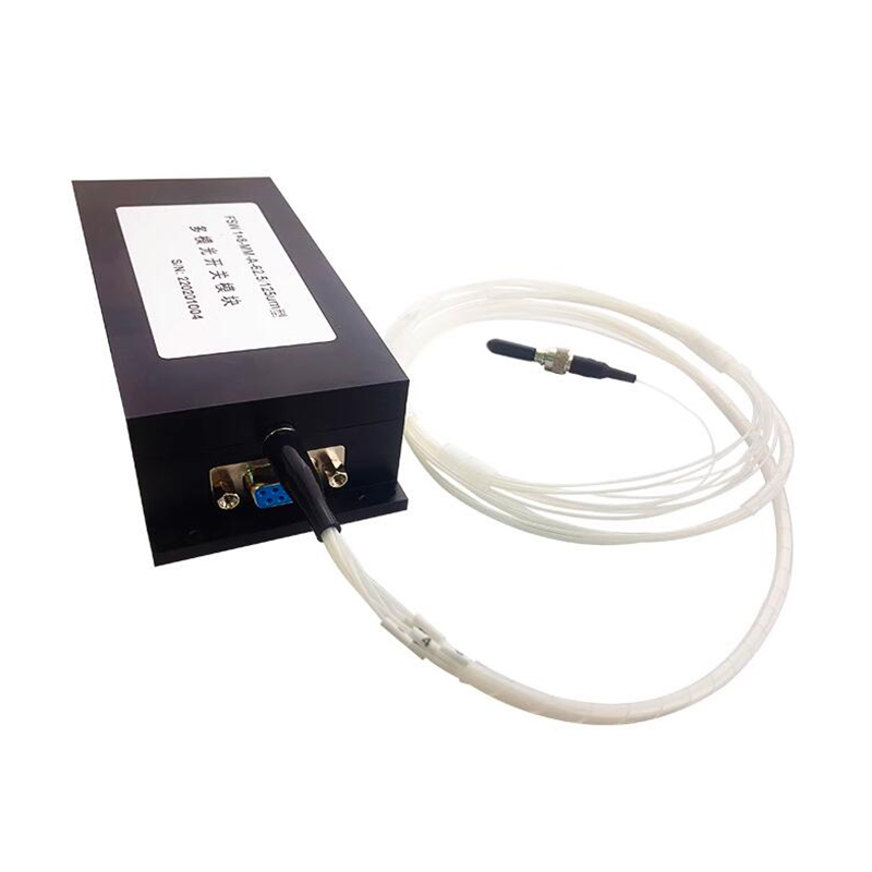
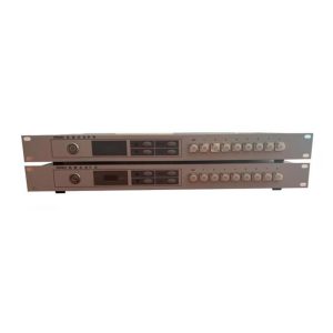
The 1×8 multi-mode optical switch module is a functional device with optical path switching function. It mainly has the following uses:
1. Multi-channel optical monitoring in optical transmission systems;
2. LAN multi-light source/detector automatic switching, light sensing multi-point dynamic monitoring system;
3. Used in optical testing systems for testing optical fibers, optical devices, networks and field engineering optical cables;
4. Optical device installation and adjustment.
[Features]
Low insertion loss
High repeatability
Modular design
Simple parallel interface control
Good isolation effect
[Specifications]
Product Name: Optical switch
Wavelength: 850nm
Fiber Type: 62.5/125um, 50/125um MM fiber , 9/125um SM fiber (Choose)
Connector: Output without connector, input SMA905 connector
Insertion Loss: ≤1.0dB
Repeatability: ≤0.05dB
Return Loss: ≥30dB
Cross Talk: ≤-70dB
Switch Time: ≤10ms(Sequential switching of adjacent channels.)
Durability: ≥10^7 times
Operating Temperature: -20~+60℃
Storage Temperature: -40~+70℃
Power Supply: 5V DC, 0.5A (Motor power supply), 5V DC, 0.1A (Digital circuit power supply
Note: This optical switch module can also be customized with single-mode fiber, please contact us.
Instruction manual:
1. The optical switch module has a control circuit interface, which is connected to the external control circuit through a 9-pin socket. The interface pin definition is shown in Table 1. Pay attention to the definition of each pin, and refer to the diagram below for specific wiring.
2. The optical switch module has an input and output optical fiber bundle, and the optical fiber diameter is .0.9mm. The input fiber (public fiber) is marked with the 0 mark, and the output fiber is marked with the 1, 2, and 8 marks respectively, indicating 8 corresponding output fibers.
3. After the power is turned on, the optical switch module will automatically reset. After reset, the optical path is disconnected and can be switched or reset through the data line or reset line.
4. Channel selection: Set/Reset high level, and then select channels 1~8 through D3~D0. Since the optical switch module is 1×8, when the strobe data exceeds channel 8, the module does not switch and sets Error to high level. It will not return to low level until correct data is input or Error is reset.
5. Reset operation: Set/Reset low level to perform reset operation, the optical switch module will be reset, and the optical path will be disconnected after reset.
6. After the optical switch module is powered off, the optical path will still remain on the original channel, but the insertion loss will change.
7. When the optical switch module is processing data (during reset or channel switching), /Ready is high level. After data processing is completed, /Ready is low level. When incorrect data is input, Error is high level, and Error does not return to low level until correct data is input or reset. For better control, the status of /Ready and Error needs to be monitored to understand the operation of the optical switch module.
.jpg)
.jpg)
.jpg)
.jpg)
| Weight | 5.43 kg |
|---|---|
| Fiber Type |

.jpg)
.jpg)
.jpg)
.jpg)
There are no reviews yet.